


jolinpc
-
Posts Por Dia
0.03 -
Posts
119 -
Registrado em
-
Última visita
-
Créditos EBR
186 [ Doar ]
Tipo de Conteúdo
Fórum
Downloads
Blogs
Galeria
Assinaturas
Calendário
Tudo que jolinpc publicou
-
 NVEExport.mpg Vídeo com a medição de tensões no conector da placa MAIN, com LEDs conectados e MAIN removidos. Os LEDs nunca acendem ............ Video with the measurement of voltages in the MAIN board connector, with LEDs connected and MAIN removed. The LEDs never light up ............... Video con la medicion de los voltajes en conector hacia placa MAIN, con leds conectados y MAIN quitada. Los leds en ningun momento se encienden
 -
Olá. Muito obrigado pela vossa ajuda. O logotipo não é mostrado em nenhum momento. Com a fonte e a placa de iluminação ligadas não faz nada e me lembro que no conector que vai para a PRINCIPAL as tensões estavam presentes mas estavam instáveis (verifiquei novamente mais tarde). Quando conecto a placa MAIN, as tensões ficam estáveis enquanto a luz Standby está acesa, mas em nenhum momento a TV fica ligada. Há algo que se desconecta como a energia e o ciclo recomeça do 0. ............... Hello. Thank you very much for your help. The logo is not shown at any time. With the source and lighting board connected, it does nothing and I seem to remember that in the connector that goes to the MAIN, the voltages were present but were unstable (I checked them again later). When I connect the MAIN board, the voltages become stable while the Standby light is on, but at no time does the TV stay on. There is something that disconnects like the power and the cycle starts again from 0. .................. Hola. Muchas gracias por su ayuda. El logo no se muestra en ningun momento. Con la placa fuente e iluminacion conectados, no hace nada y creo recordar que en el conector que va hacia la MAIN, lo voltajes estaban presentes pero eran inestables (luego los compruebo nuevamente). Cuando conecto la placa MAIN, los voltajes se vuelven estables mientras la luz de Standby esta encendida, pero en ningun momento el TV se mantienen encendido. Hay algo que desconecta como la alimentacion y vuelve a empezar desde 0 el ciclo
-
Muito obrigado pela sua resposta e pela sua ajuda. Revisei as soldas da área e tudo continua igual. Não tenho osciloscópio, só tenho frequencímetro, então tenho que tentar consertar sem ele. Conectei a fonte ao MAIN e realizei as medições no CNM803 com ele conectado, sendo o comportamento o seguinte: Quando a luz de espera está acesa, as tensões estão estáveis: A13V...12,7V Contagem de falhas...3,2V ANA DIM...3.2V OD_LIGADO/DESLIGADO ... 3,2V PWM_BLU...0V Ligado...3,2V Porém, quando a luz de standby apaga os valores são: A13V...a tensão cai para 3,1V depois sobe para 9V e depois para 12,7V porque volta ao modo de espera Contagem de falhas, ANA DIM, OD_ ON/OFF... Cai para 0V PWM_BLU .. Quando o LED standby apaga, ele tem um pico entre 1,5V e 3V, e depois cai para 0V. Quando o LED standby acende novamente, os 3,2V retornam Consegui outra fonte (supostamente funcionando bem), e as medições sem nada conectado também ficam instáveis, por isso interpreto que esse modelo de fonte, para ter tensões estáveis, deve estar conectado à PRINCIPAL. Da mesma forma, ao conectar a nova fonte utilizada ao MAIN, o comportamento é o mesmo. Já tentei conectar o MAIN e os LEDs, deixando o flex do t-con desconectado mas o erro continua. É possível que a falha esteja no PRINCIPAL? ...... Thank you very much for your response and your help. I have reviewed the welds in the area, and everything remains the same. I don't have an oscilloscope, I only have a frequency meter, so I have to try the repair without it. I have connected the source to the MAIN and performed the measurements on CNM803 with it connected, the behavior being as follows: When the standby light is on, the voltages are stable: A13V...12.7V Fail Count...3.2V ANA DIM...3.2V OD_ON/OFF ... 3.2V PWM_BLU...0V PowerON...3.2V However, when the standby light goes off the values are: A13V...the voltage drops to 3.1V then rises to 9V and then to 12.7V because it comes back on standby Fail Count, ANA DIM, OD_ ON/OFF ... Drop to 0V PWM_BLU .. When the standby LED turns off, it has a peak between 1.5V and 3V, and then drops to 0V. When the standby LED comes back on, the 3.2V returns I have been able to get another source (supposedly working well), and the measurements without anything connected are also unstable, which is why I interpret that this source model, to have stable voltages, must be connected to the MAIN. Likewise, when connecting the new source used to the MAIN, the behavior is the same. I have tried connecting the MAIN and the LEDs, leaving the flex to t-con disconnected but the error continues. Is it possible that the fault is in the MAIN? ....................... Muchas gracias por su respuesta y su ayuda. He repasado las soldaduras de la zona, y todo sigue igual. Osciloscopio no tengo, solo tengo frecuencimetro, con lo cual, tengo que intentar la reparacion sin el mismo. He conectado la fuente a la MAIN y realizado las mediciones en CNM803 con ella conectada siendo el comportamiento el siguiente: Cuando la luz de stand by esta encendida, los voltajes son estables: A13V ... 12,7V Fail Count ... 3,2V ANA DIM ... 3,2V OD_ON/OFF ... 3,2V PWM_BLU ... 0V PowerON ... 3,2V En cambio cuando la luz de standby se apaga los valores son: A13V ... el voltaje cae a 3,1V luego sube a 9V y luego a los 12,7V porque se vuelve a encender standby Fail Count, ANA DIM, OD_ ON/OFF ... Caen a 0V PWM_BLU .. En el momento de apagarse el led stanby, tiene un pico a entre 1,5V y 3V, y luego cae a 0V. Cuando el led standby vuelve a encender, regresan los 3,2V He podido conseguir otra fuente (supuestamente funcionando bien), y las mediciones sin nada conectado tambien son inestables, con lo cual interpreto que este modelo de fuente, para tener los voltajes estables, debe estar conectada a la MAIN. Igualmente, al conectar la nueva fuente usada a la MAIN, el comportamiento es el mismo. He probado a conectar la MAIN y los leds, dejando desconectado el flex hacia t-con pero el fallo continua. ¿Es posible que el fallo este en la MAIN?
-
Olá pessoal. Tenho uma televisão Samsung UE48JU6410U que, quando ligada, o LED standby começa a piscar e permanece em loop sem nunca entrar no modo de suspensão ou ligar. Possui uma fonte de alimentação BN44-00807D. Verifiquei se havia algum diodo ou mosfets em curto, mas tudo parece correto. Troquei os capacitores, CM855 por CM858 (470uf 25V), CM862 e CM863 (33uf 250V), C9371 (47uf) 50V, porque embora fisicamente parecessem bem, quando a fonte é conectada ao PRINCIPAL, leves ruídos de clique são ouvidos em aquela área. O ruído coincide da seguinte forma: quando o LED de standby apaga você pode ouvi-lo, e quando o LED está aceso ele fica silencioso. Com a fonte de alimentação vazia (sem nada conectado), verifiquei as tensões no conector CNM803, e todas as tensões estão muito instáveis, exceto o pino 2 (ANA_DIM), que está estável em 3,2V O valor no restante dos pinos é: Pinos 3, 5, 7, 9 (A13V)... Muito instável Pino 4 OD_ON/OFF ... 2,5V a 4V instável Pino 1 Fail_count...0V Pino 6 PWM Blu...2V a 3,5V instável Pino 8 LIGADO .... 3V a 5V instável Alguém pode me ajudar? .............................. Hello everyone. I have a Samsung UE48JU6410U television, which, when the power is turned on, the standby LED starts flashing and remains in a loop without ever entering sleep mode or turning on. It has a BN44-00807D power supply. I checked to see if there were any shorted diodes or mosfets, but everything seems correct. I have replaced the capacitors, CM855 to CM858 (470uf 25V), CM862 and CM863 (33uf 250V), C9371 (47uf) 50V, because although physically they seemed fine, when the supply is connected to the MAIN, slight clicking noises are heard in that area . The noise coincides in the following way: when the standby LED goes off you can hear it, and when the LED is on it is silent. With the Power Supply empty (with nothing connected), I have checked the voltages on the CNM803 connector, and all the voltages are very unstable except pin 2 (ANA_DIM), which is stable at 3.2V The value on the rest of the pins are: Pins 3, 5, 7, 9 (A13V)... Very unstable Pin 4 OD_ON/OFF ... 2.5V to 4V unstable Pin 1 Fail_count...0V Pin 6 PWM Blu...2V to 3.5V unstable Pin 8 POWER ON .... 3V to 5V Unstable Can somebody help me? ............................... Hola a tod@s. Tengo el televisor Samsung UE48JU6410U, el cual, al conectar la alimentacion, el led de standby empieza a parpadear y se queda en bucle sin llegar a entrar en modo reposo y sin llegar a encender. Tiene una fuente de alimentacion BN44-00807D. He mirado si había algun diodo o mosfet en corto, pero todo parece correcto. He sustituido los condensadores, CM855 a CM858 (470uf 25V), CM862 y CM863 (33uf 250V), C9371 (47uf) 50V, porque aunque fisicamente parecían bien, cuando esta conectada la fuente a la MAIN, se escucha unos leves chasquidos por esa zona. El ruido coincide de la siguiente forma: cuando el led de standby se apaga se escucha, y cuando el led esta encendido esta en silencio. Con la Fuente de alimentacion en vacio (sin nada conectado), he comprobado los voltajes en el conector CNM803, y todos los voltajes estan muy inestables excepto el pin 2 (ANA_DIM), que esta estable en 3,2V El valor en el resto de pines son: Pines 3, 5, 7, 9 (A13V) ... Muy inestable Pin 4 OD_ON/OFF ... 2,5V a 4V inestables Pin 1 Fail_count ... 0V Pin 6 PWM Blu ... 2V a 3,5V inestables Pin 8 POWER ON .... 3V a 5V Inestables ¿Alguien me puede ayudar?
-
em análise SPC GRAVITY SE / BND-A863-CT V5.0 / I need a photo of the charging connector area
jolinpc postou um tópico em Tablet, Ipad
Um cliente me trouxe SPC GRAVITY SE TABLET com placa-mãe BND-A863-CT V5.0. O tablet apresenta problemas de carregamento e já foi manuseado anteriormente por outras pessoas, deixando a área do conector de carregamento em mau estado. Preciso de uma foto da área do conector de carregamento, para comparar com a foto anexa e verificar se falta algum componente inicialmente. Obrigado .................. A customer brought me SPC GRAVITY SE TABLET with BND-A863-CT V5.0 motherboard. The tablet has charging problems and has been tampered with before by other people, leaving the charging connector area in a poor state. I need a photo of the charging connector area, to compare it with the attached photo and check if any component is initially missing. Thank you .......... Un cliente me trajo la TABLETA SPC GRAVITY SE con placa base BND-A863-CT V5.0. La tablet tiene problemas de carga y ha sido manipulada antes por otras personas, dejando la zona del conector de carga en mal estado. Necesito una foto de la zona del conector de carga, para compararla con la foto adjunta y comprobar si falta algún componente inicialmente. Gracias
-
resolvido HP G62-460SS / DAAX1JMB8C0 / No power
jolinpc respondeu o tópico de jolinpc em Casos resolvidos - Notebooks
Bem, parece ter encontrado o culpado por tanta tontura. Troquei o PC201 que fica do lado oposto do PU4 e na linha +5V_ALWP, e até agora não desligou novamente ...... Well, it seems to have found the culprit for so much dizziness. I have replaced PC201 which is just on the opposite side of PU4 and on the +5V_ALWP line, and so far it has not turned off again ............... Pues parece haber encontrado al culpable de tanto mareo. He sustituido PC201 que esta justo en el lado opuesto de PU4 y en la linea +5V_ALWP, y de momento no se ha vuelto a apagar- 17 respostas
-
- 1
-

-
- g62-460ss
- daax1jmb8c0
- (mais 1)
-
resolvido HP G62-460SS / DAAX1JMB8C0 / No power
jolinpc respondeu o tópico de jolinpc em Casos resolvidos - Notebooks
Troquei o PU4 por um novo e o problema acima foi corrigido. A energia não foi mais desconectada depois de ligar, desligar e remover a energia. Ligava e desligava sem problemas. Após a montagem, a equipe falhou novamente e o PU4 estava esquentando muito. Troquei por um novo. Com a placa-mãe totalmente desmontada (somente memória), conecto a alimentação e a ventoinha do dissipador, conecto a alimentação. O led do jack liga e sem apertar power nem nada, depois de 60 segundos o led do jack desliga. Se eu tirar a energia e ligar de novo, o led liga de novo, mas dessa vez depois de 5 segundos ele desliga .............. I have exchanged PU4 for a new one, and the above problem was corrected. Power was no longer disconnected after turning power on, off, and removing power. It turned on and off with no problem. After assembling, the team failed again and PU4 was getting very hot. I have exchanged it for a new one. With the motherboard completely disassembled (memory only), I connect the power and heatsink fan, I connect the power. The jack led turns on and without pressing power or anything, after 60 seconds the jack led turns off. If I remove power and put it back on, the led turns on again, but this time after 5 seconds it turns off ........... He cambio PU4 por otro nuevo, y el problema anterior se corrigió. Ya no se desconectaba la alimentación tras encender, apagar y retirar alimentación. Encendía y apagaba sin problemas. Tras ensamblar, el equipo a vuelto a fallar y PU4 se ponía muy caliente. Lo he vuelto a cambiar por otro nuevo. Con la placa base completamente desmontada (solo memoria), conecto la alimentación y ventilador disipador, conecto la alimentacion. Se enciende el led del jack y sin pulsar power ni nada, a los 60 segundo se apaga el led jack. Si quito alimentación y la vuelvo a poner, vuelve a enceder el led, pero esta vez a los 5 segundos se apaga -
resolvido HP G62-460SS / DAAX1JMB8C0 / No power
jolinpc respondeu o tópico de jolinpc em Casos resolvidos - Notebooks
Esse problema pode estar relacionado ao PU4 com defeito? trocá-lo por um novo? O chip que está soldado atualmente é o original, e talvez, com o processo de dessoldagem, tenha sido parcialmente reativado internamente. ........... That problem can be related to defective PU4? change it for a new one? The chip that is currently soldered is the original one, and perhaps, with the desoldering process, it was partly reactivated internally. ............ Ese prolema puede ser relacionado con PU4 defectuoso? Lo cambio por uno nuevo? El chip que actualmente esta soldado es el original, y a lo mejor, con el proceso de desoldar, internamente se reactivó en parte. -
HP G62-460SS / DAAX1JMB8C0 / No power
jolinpc respondeu o tópico de jolinpc em Casos resolvidos - Notebooks
Quando o equipamento liga ele fica rodando o tempo todo sem problemas. Quando desligo pelo botão power, retiro a corrente e reconecto, é quando não liga mais, até ficar um tempo desconectado da fonte de alimentação. A todo momento está sendo testado apenas com a placa mãe fora do equipamento e sem bateria, direto na energia (O cliente não possui bateria) Quando isso acontece, tentei fontes diferentes, incluindo um alimentador HP original, mas o resultado é o mesmo. Anexo as medidas : Pin 1: 1,9V Pin 2: 4,9V Pin 4: 13,9V Pin 6: 19,4V Pin 7: 4,9V Pin 12: 1,4V Pin 14: 4,8V Pin 17: 4,5V Pin 19/20/23/24: 4,9V Pin 27: 4,8V Pin 31: 0,09V Pin 32: 4,9V Todos os outros pinos 0V ................ When the equipment turns on it stays running all the time without problems. When I turn it off from the power button, I remove the current and reconnect it, it is when it no longer turns on anymore, until it remains disconnected from the power supply for a while. At all times it is being tested only with the motherboard outside the equipment and without battery, directly to power (The client does not have a battery) When it does happen, I have tried different sources, including an original HP feeder, but the result is the same. I attach the measurements: .................... Cuando el equipo enciende se queda funcionando todo el tiempo sin problemas. Cuando lo apago desde el boton power, le quito la corriente y la vuelvo a conectar, es cuando ya no enciende mas, hasta que se quede desconectado de la alimentacion un tiempo. En todo momento esta siendo probado solo con la placa base fuera del equipo y sin bateria, directamente a alimentacion (El cliente no tiene bateria) Cuando sucede, he probado con otras fuentes distintas, entre ellas, un alimentador original HP, pero el resultado es el mismo. Te adjunto las medidas:- 17 respostas
-
- 1
-
-
- g62-460ss
- daax1jmb8c0
- (mais 1)
-
HP G62-460SS / DAAX1JMB8C0 / No power
jolinpc respondeu o tópico de jolinpc em Casos resolvidos - Notebooks
El equipo me empieza a volver un poco loco porque enciende bien pero cuando quiere no vuelve a encender. Ayer, después de que arrancó bien, lo apagué y desconecté la alimentación. Después de un tiempo apagado, volví a conectar la alimentación, el led de power jack se encendió por un segundo y luego de que se apagó el led, el equipo ya no responde y en PU4 los voltajes volvieron a ser los mismos, con la diferencia que el pin 1 no está corto . Hoy llego, y el equipo ya prende bien Como referência, quando o equipamento liga bem, se eu desligo, tiro a energia e ligo novamente, o equipamento não liga mais ....................... El equipo me empieza a volver un poco loco porque enciende bien pero cuando le da la gana no vuelve a encender. Ayer, después de comenzar bien, apagué y desconecté la alimentación. Después de un tiempo apagado, volví a conectar la corriente, el led de power jack se encendió por un segundo y luego de que se apagó el led, el equipo ya no responde y en PU4 los voltajes volvieron a ser los mismos, con la diferencia que el pin 1 no está corto . Hoy me ha llegado, y el equipo ahora prende bien As a reference, when the equipment turns on well, if I turn it off, remove the power and put it back on, the equipment no longer turns on .................... El equipo esta empezando a volverme un poco loco porque enciende bien pero cuando le da la gana, vuelve a no encender. Ayer después de encender bien, apagué y desconecté la alimentación. Después de un tiempo apagado, volví a conectar alimentación, led jack power se encendió por un segundo y después de apagarse el led, el equipo ya no responde y en PU4 los voltajes volvían a ser los mismos, con la diferencia de que el pin 1 no está en corto. Hoy he llegado, y el equipo ahora enciende bien Como referencia, cuando el equipo enciende bien, si lo apago, le quito la alimentación y la vuelvo a poner, el equipo ya no enciende -
HP G62-460SS / DAAX1JMB8C0 / No power
jolinpc respondeu o tópico de jolinpc em Casos resolvidos - Notebooks
Após ligar e desligar, e deixá-lo um tempo parado, ele volta ao início, apenas tensão nos pinos 4 e 6 do PU4. Diferente de antes, no pino 1 não tem curto e no PL5 e PL9 tenho uma resistência baixa, tudo isso tomando como referência a ponta positiva no terra e negativa nas bobinas. ................... After turning it on and off, and leaving it idle for a while, it is back to the beginning, only voltage on pin 4 and 6 of PU4. Unlike before, in pin 1 there is no short and in PL5 and PL9 I have a low resistance, all this taking as reference the positive tip in ground and negative in coils. ....................... Después de encender y apagar, y de dejar un rato en reposo, vuelve a estar como al principio, solamente voltaje en pin 4 y 6 de PU4. A diferencia con antes, en el pin 1 no hay corto y en PL5 y PL9 tengo una resistencia baja, todo esto tomando como referencia la punta positivo en masa y negativo en bobinas. -
HP G62-460SS / DAAX1JMB8C0 / No power
jolinpc respondeu o tópico de jolinpc em Casos resolvidos - Notebooks
Soldei novamente o chip antigo. Antes de ligar, verifiquei se o pino 1 não estava em curto. Eu alimentei e agora todas as tensões aparecem e o equipamento liga. É possível que a aplicação de calor na solda e na dessoldagem tenha restaurado internamente o chip? Seria aconselhável alterá-lo? .............. I have re-soldered the old chip. Before turning on I checked that pin 1 was not shorted. I have fed, and now all the voltages appear and the equipment turns on. Is it possible that applying heat to solder and desolder has internally restored the chip? Would it be advisable to change it? ................. He soldado nuevamente el viejo chip. Antes de encender he comprobado que el pin 1 no estaba en corto. He alimentado, y ahora aparecen todos lo voltajes y el equipo enciende. Es posible que al aplicar el calor para soldar y desoldar se haya reestaurado internamente el chip? Sería recomendable cambiarlo? -
HP G62-460SS / DAAX1JMB8C0 / No power
jolinpc respondeu o tópico de jolinpc em Casos resolvidos - Notebooks
Eu extraí o PU4 novamente. Com o chip sem solda, não há curto no pino 1 da placa-mãe, mas também não há curto no chip. No original, também não há. é normal? .................... I have extracted PU4 again. With the chip unsoldered, there is no short on pin 1 on the motherboard, but there is no short on the chip either. In the original, there isn't either. It is normal? .................. He extraido nuevamente PU4. Con el chip desoldado, no hay corto en el pin 1 de la placa base, pero en el chip tampoco lo hay. En el original, tampoco lo hay. ¿es normal? -
HP G62-460SS / DAAX1JMB8C0 / No power
jolinpc respondeu o tópico de jolinpc em Casos resolvidos - Notebooks
Eu levantei o PC86 e o curto permanece. O condensador está ok. PU4 danificado novamente? .................... I have raised PC86 and the short remains. The condenser is ok. PU4 damaged again? .............. He levantado PC86 y el corto premanece. El condensador esta ok. PU4 nuevamente dañado? -
HP G62-460SS / DAAX1JMB8C0 / No power
jolinpc respondeu o tópico de jolinpc em Casos resolvidos - Notebooks
O pino 1 está em curto. Vou rever o PC86 ...................... Pin 1 is shorted. I'm going to review PC86 .......... Pin 1 esta en cortocircuito. Voy a revisar PC86 -
Olá, recebi este notebook HP G62-460SS com placa-mãe DAAX1JMB8C0, com PD19 queimado e sem resposta. Depois de substituir o PD19 e ter 19V no Vin, ele ainda não liga. +5V_ALWP e +3V_ALWP não estão presentes. No PU4 (RT8206B) só tenho tensão no pino 4...13,9V e no pino 6...19,5V O restante dos pinos está em 0V, exceto os pinos 12 e 15 que possuem apenas 0,02V Substituí o PU4 mas os valores são os mesmos. .............................. Hello, I have received this HP G62-460SS laptop with DAAX1JMB8C0 motherboard, with PD19 burned and without any response. After replacing PD19 and having 19V on Vin it still doesn't turn on. +5V_ALWP and +3V_ALWP are not present. On PU4 (RT8206B) I only have voltage on Pin 4...13.9V and Pin 6...19.5V The rest of the pins are at 0V except for pin 12 and 15 that have only 0.02V I have substituted PU4 but the values are the same. ................................. Hola, me ha llegado este protatil HP G62-460SS con placa base DAAX1JMB8C0, con PD19 quemado y sin respuesta alguna. Tras sustituir, PD19 y tener 19V en Vin sigue sin encender. +5V_ALWP y +3V_ALWP no estan presentes. En PU4 (RT8206B) olo tengo voltaje en Pin 4 ... 13,9V y Pin 6 ... 19,5V El resto de pines estan a 0V execpto pin 12 y 15 que tienen a penas 0,02V He sustituido PU4 pero los valores son los mismos.
-
resolvido Samsung UE32C5100 No Power No Standby
jolinpc respondeu o tópico de jolinpc em Casos resolvidos - TVs
Olá! A TV já está funcionando. O problema estava mesmo no Main, especificamente nas informações na EPROM do IC402. Consegui fazer um dump, e depois de reprogramar externamente, o led standby está presente novamente, e a Televisão funciona normalmente. Aqui deixo o link do arquivo enviado, caso alguém precise. Saudações e obrigado ....... Hello! The TV is already working. The problem was indeed in the Main, specifically in the information in the EPROM of the IC402. I have been able to get a dump, and after reprogramming externally, the standby led is present again, and the Television works normally. Here I leave the link to the uploaded file, in case someone else needs it. Greetings and thanks ......... Hola! Ya esta funcionando la TV. El problema efectivamente estaba en la Main, concretamente en la informacion de la EPROM del IC402. He podido conseguir un dump, y tras reprogramar de forma externa, el led de standby vuelve a estar presente, y la Television trabaja normal. Aqui dejo el enlace al archivo subido, por si alguien mas lo necesita. Saludos y gracias -
flash Samsung / UE32C5100QW Versión CN01 / BN41-01378A
jolinpc postou um tópico em Gerenciador de arquivos
Samsung / UE32C5100QW Versión CN01 / BN41-01378A Ver archivo O arquivo compactado contém 3 dumps correspondentes aos ICs: IC402, IC501, IC502 O Dump IC402 está verificado e 100% funcional. Testado em Samsung UE32C5100 com MAIN BN41-01378A e painel T320FAE1-DB ........................... The compressed file contains 3 dumps corresponding to the ICs: IC402, IC501, IC502 The IC402 Dump is verified and 100% functional. Tested on Samsung UE32C5100 with MAIN BN41-01378A and panel T320FAE1-DB ................ El archivo comprimido contiene 3 dump correspondientes a los IC: IC402, IC501, IC502 El Dump del IC402 esta comprobado y 100% funcional. Comprobado en Samsung UE32C5100 con MAIN BN41-01378A y panel T320FAE1-DB Submitter jolinpc Submitted 19/01/23 Categoría Samsung -
0 downloads
O arquivo compactado contém 3 dumps correspondentes aos ICs: IC402, IC501, IC502 O Dump IC402 está verificado e 100% funcional. Testado em Samsung UE32C5100 com MAIN BN41-01378A e painel T320FAE1-DB ........................... The compressed file contains 3 dumps corresponding to the ICs: IC402, IC501, IC502 The IC402 Dump is verified and 100% functional. Tested on Samsung UE32C5100 with MAIN BN41-01378A and panel T320FAE1-DB ................ El archivo comprimido contiene 3 dump correspondientes a los IC: IC402, IC501, IC502 El Dump del IC402 esta comprobado y 100% funcional. Comprobado en Samsung UE32C5100 con MAIN BN41-01378A y panel T320FAE1-DB-
- 2
-
-
- samsung
- ue32c5100qw
- (mais 3)
-
resolvido Samsung UE32C5100 No Power No Standby
jolinpc respondeu o tópico de jolinpc em Casos resolvidos - TVs
Eu segui suas instruções, para forçar a fonte de alimentação a ligar sem estar conectada ao PRINCIPAL, e de fato as fontes secundárias estão começando a funcionar e tenho todas as tensões 12V...13V 5,3 V ... 5,1 V Vamp...13V MVP ... 5V BLON .... 2.8V No DET não tenho nada. Deve haver algum valor? ............................... I have followed your instructions, to force the Power Supply to turn on without being connected to the MAIN, and indeed the secondary sources are starting to work and I have all the voltages 12V ...13V 5.3V ... 5.1V Vamp...13V MVP ... 5V BLON .... 2.8V In DET I have nothing. Should there be any value? ............... He seguido tus instrucciones, para forzar el encendido de la Fuente de Alimentación sin estar conectada a la MAIN, y efectivamente ya empiezan a trabajar las fuentes secundarias y tengo todos los voltajes 12V ...13V 5,3V ... 5,1V Vamp ... 13V PVM ... 5V BLON .... 2,8V En DET no tengo nada. ¿Debería haber algún valor? -
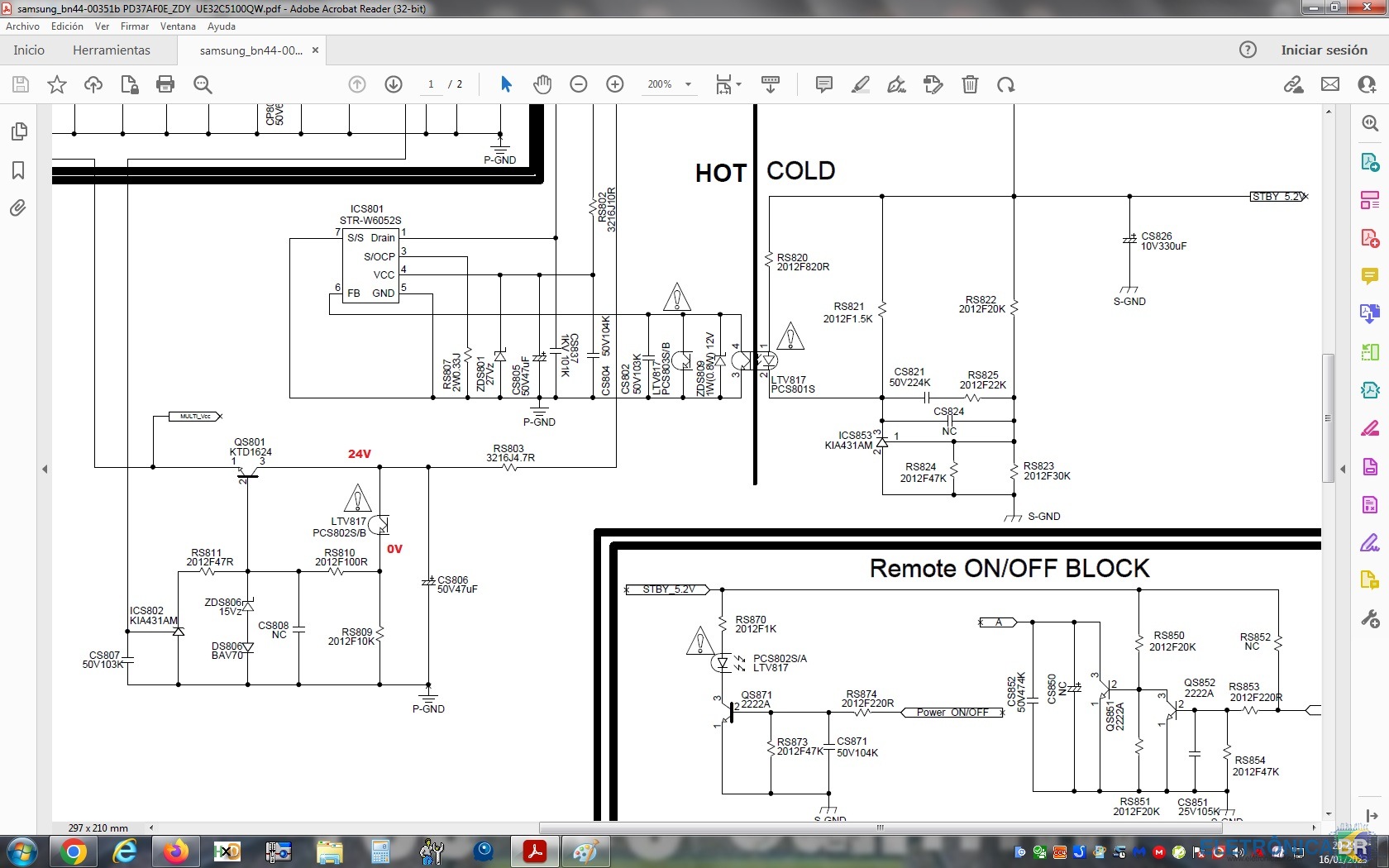
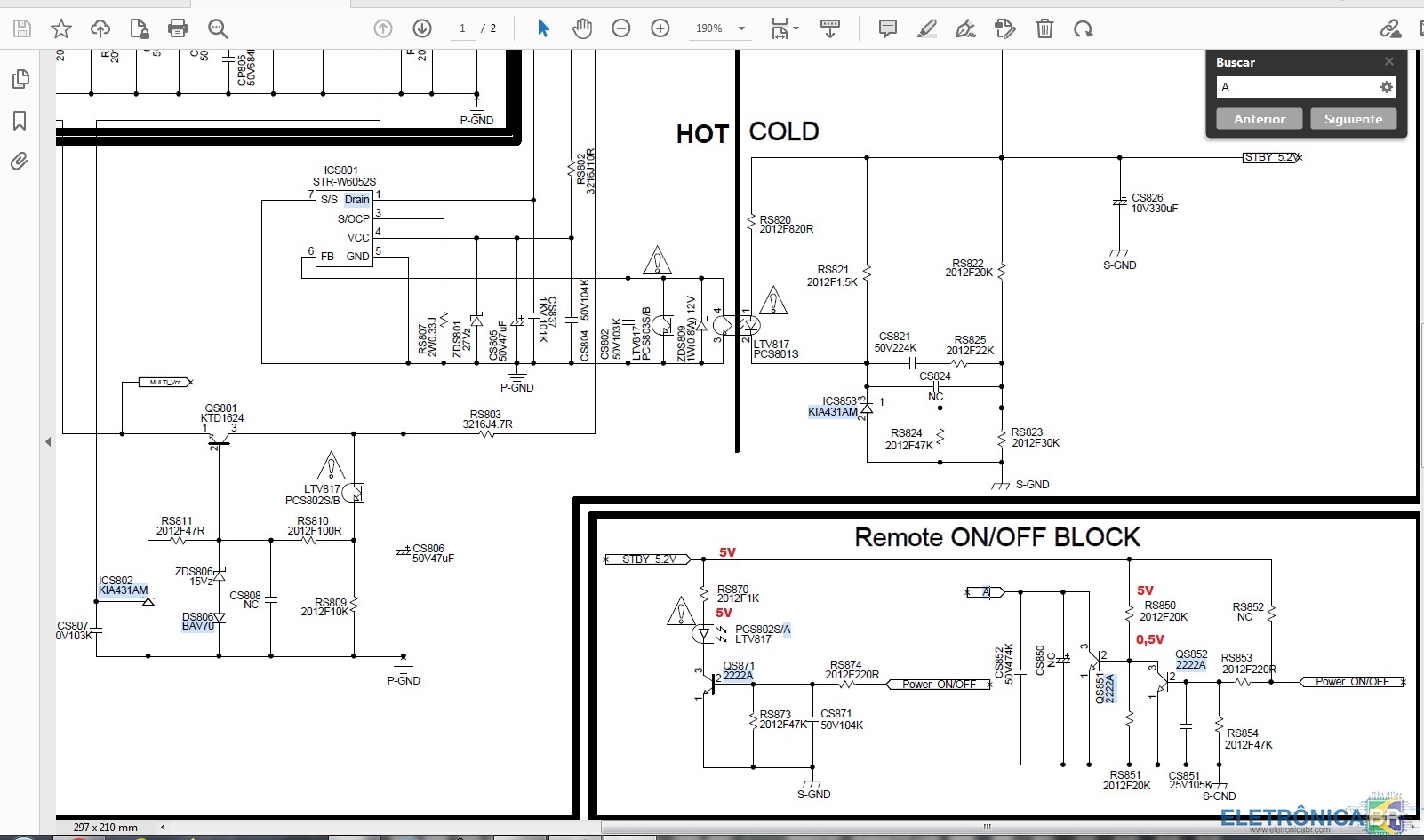
Olá pessoal! Eu tenho essa TV Samsung UE32C5100 com uma fonte de alimentação BN44-00351R, que não liga a luz de standby não faz nada. Já verifiquei os diodos, resistores de baixo valor e mosfets, e não encontrei nenhum em curto, nem aberto, e com valores corretos. No conector CNM801 que vai para a placa PRINCIPAL só tenho o valor StandBy (Pino 16) em 5V. Retirei a Fonte de Alimentação e fiz as medições de tensão indicadas nas fontes anexas. Parece-me que em uma extremidade do RM820 tenho 20V e na outra 0V. Eu medi o valor do resistor RM820 e está bom, e verifiquei a resistência em relação ao terra e não está em curto. Com tudo conectado, medi o valor no receptor de infravermelho (3,3V), e quando pressiono o controle remoto esse valor cai para 2,5V. Esse valor está correto? Alguém pode me explicar o funcionamento dos sinais nesta fonte? Obrigado ............................... Hello everyone! I have this Samsung UE32C5100 TV with a BN44-00351R power supply, which does not turn on the standby light does nothing. I have checked the diodes, low value resistors and mosfets, and I have not found any shorted, nor open, and with correct values. In the CNM801 connector that goes to the MAIN board I only have the StandBy value (Pin 16) at 5V. I have removed the Power Supply and have made the voltage measurements indicated on the attached sources. It strikes me that at one end of the RM820 I have 20V and at the other 0V. I have measured the value of the RM820 resistor and it is fine, and I have checked the resistance with respect to ground and it is not shorted. With everything connected, I have measured the value on the infrared receiver (3.3V), and when I press the remote this value drops to 2.5V. Is that value correct? Can someone explain to me the operation of the signals in this source? Thanks .......................................... Hola a tod@s! Tengo éste TV Samsung UE32C5100 con fuente de alimentación BN44-00351R, el cual no enciende luz standby no hace nada. He revisado los diodos, resistencias de bajo valor y mosfet, y no he encontrando ninguno en corto, ni tampoco abierto, y con valores correctos. En el conector CNM801 que va a placa MAIN solo tengo el valor de StandBy (Pin 16) en 5V. He extraído la Fuente de alimentación y he realizado las mediciones de voltaje que se indican en las fuentes adjuntas. Me llama la atención, que en un extremo de RM820 tengo 20V y en el otro 0V. He medido el valor de la resistencia RM820 y esta bien, y he comprobado la resistencia con respecto a masa y no está en corto. Con todo conectado, he medido el valor en el receptor infrarojo (3,3V), y al pulsar en el mando este valor cae a 2,5V. ¿Ese valor es correcto? ¿Alguien me puede explicar el funcionamiento de las señales en esta fuente?
-
Hp pavilion 23 aio b210br- preciso tela alguem sabe onde achar?
jolinpc respondeu o tópico de piquita em Motherboards, PCs, All in One & Cia
Olá Para encontrar a tela procure-a pela referência da própria tela. Para o modelo all-in-one, será mais difícil e limitado. Observe que outros modelos multifuncionais podem montar a mesma tela Desmonte o tudo em um e procure a referência na tela Saudações ............... Hello To find the screen look for it by the reference of the screen itself. For the all-in-one model, it will be more difficult and limited. Please note that other all-in-one models can mount the same screen Disassemble the all in one and look for the reference on the screen Greetings ................ Hola Para encontrar la pantalla buscalo por la referencia de la propia pantalla. Por el modelo del todo en uno, va a ser más dificil y limitado. Ten en cuenta que otros modelos de todo en uno pueden montar la misma pantalla Desmonta el todo en uno y busca la referencia en la pantalla Saludos -
em análise Acer E5-574G - DA0ZRWMB6G0 - no vídeo signal
jolinpc respondeu o tópico de jolinpc em Notebook's
Tentei outras Bios e obtive o mesmo resultado, ou em outros momentos, a mudança do tom da tela desaparece. Reprogramei sua Bios original e tive que começar a fazer medições novamente a partir de 0, porque +VCCGT não está presente novamente. Nesta ocasião, FCCM_B não está presente. Verifiquei a resistência ao terra do FCCM_B, e está alta, então deduzo que PU1 (ISL95859HRTZ), está ruim. Eu pedi o chip e vai demorar 2 semanas. Enquanto eu vou fazer outras verificações Obrigada ....................... I have tried other Bios and I get the same result, or at other times the screen tone change disappears. I have reprogrammed its original Bios and had to start taking measurements again from 0, because +VCCGT is not present again. On this occasion, FCCM_B is not present. I have checked the resistance to ground of FCCM_B, and it is high, so I deduce that PU1 (ISL95859HRTZ), is bad. I have ordered the chip and it will take 2 weeks. While I will do other checks Thank you ................... He probado otras Bios y obtengo el mismo resultado, o en otras ocasiones, el cambio de tono de la pantalla desaparece. He vuelto a programar su Bios original y he tenido que empezar nuevamente a tomar mediciones desde 0, porque +VCCGT no esta presente otra vez. En esta ocasión, FCCM_B no está presente. He comprobado la resistencia con respecto a masa de FCCM_B, y es alta, por lo cual, deduzco que PU1 (ISL95859HRTZ), está en mal estado. He pedido el chip y tardará 2 semanas. Mientras haré otras comprobaciones Gracias -
em análise Acer E5-574G - DA0ZRWMB6G0 - no vídeo signal
jolinpc respondeu o tópico de jolinpc em Notebook's
Preciso montar a BIOS com a imagem baixada da Acer. Em outras ocasiões usei a ferramenta phoenix, ou recortei e colei áreas da BIOS depois de comparar, mas desta vez não consegui. A bios baixada da Acer tem 6.794 Kb de tamanho, enquanto a bios de backup do laptop tem 8.192 Kb. Alguém pode me orientar como fazer dessa vez? ...................... I need to mount the BIOS with the image downloaded from Acer. On other occasions I have used the phoenix tool, or cut and pasted areas of the BIOS after comparing, but this time I can't get it. Acer's downloaded bios is 6794 Kb in size, while the laptop's backup Bios is 8192 Kb in size. Can someone guide me how to do it this time? ........................... Necesito montar la BIOS con la imagen bajada desde Acer. En otras ocasiones he utilizado la herramienta phoenix, o cortado y pegado zonas del BIOS tras comparar, pero en esta ocasión no logro conseguirlo. La bios bajada de Acer tiene un tamaño de 6794 Kb, mientras que la copia de seguridad del Bios del portátil tiene un tamaño de 8192 Kb. Alguien me puede orientar como hacerlo en ésta ocasión? -
em análise Acer E5-574G - DA0ZRWMB6G0 - no vídeo signal
jolinpc respondeu o tópico de jolinpc em Notebook's
Tentei decodificar o arquivo bios do site oficial mas devo estar cometendo algum erro e a ferramenta phoenix não o gera corretamente, então tentei baixar e salvar o arquivo que outro colega carregou neste fórum, com o ME limpo e extraído de um arquivo de atualização. Após salvar, o resultado é o mesmo Este é o arquivo baixado ...... I have tried to decode the bios file from the official website but I must be making some mistake and phoenix tool does not generate it correctly, so I have tried to download and save the file that another colleague has uploaded in this forum, with the ME clean and extracted from an update file. After saving, the result is the same This is the downloaded file .................. He intentado decodificar el archivo bios de la web oficial pero, debo estar cometiendo algun error y phoenix tool no me lo genera correctamente, así que he probado a bajar y grabar el archivo que otro compañero a subido en este foro, con la ME limpia y extraido de un archivo de actualizacion. Tras grabar, el resultado es el mismo Éste es el archivo bajado


SOBRE O ELETRÔNICABR
Técnico sem o EletrônicaBR não é um técnico completo! Leia Mais...