


Vijay Arockia Raj Vijay
-
Posts Por Dia
0.1 -
Posts
327 -
Registrado em
-
Última visita
-
Vitórias
4 -
Créditos EBR
1,685 [ Doar ]
Tipo de Conteúdo
Fórum
Downloads
Blogs
Galeria
Assinaturas
Calendário
Tudo que Vijay Arockia Raj Vijay publicou
-

em análise Philco - PH24D20DG - Trava na inicialização
Vijay Arockia Raj Vijay respondeu o tópico de lfvidal em TVs de PLASMA, LCD, LED e CRT
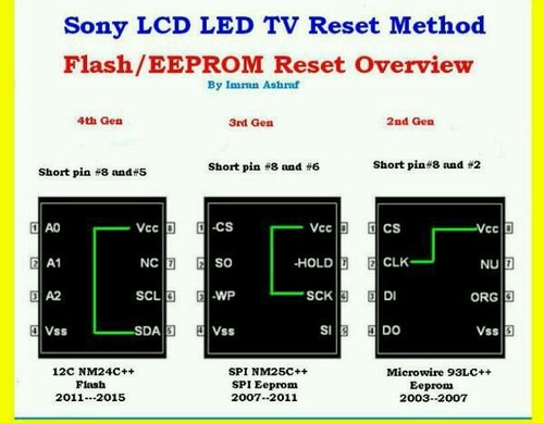
https://eletronicabr.com/files/file/26458-reset-flash-ics/ -
Versão 1.0.0
43 downloads
reset flash ics -
View File reset flash ics reset flash ics Submitter Vijay Arockia Raj Vijay Submitted 11/29/2017 Category Plasma, LCD, Led and CRT TVs
-
dúvida Brother 8085 e 8070/erro 71
Vijay Arockia Raj Vijay respondeu o tópico de Lucas Monge em Impressoras e Copiadoras
The Print Unable 71 error message has to deal with laser unit polygon motor. On most Brothermachines the laser unit doesn’t start up till it starts to print. When the motor starts up it typically sounds like a CPU fan starting up in the middle of the machine. The polygon motor usually runs 20 to 40,000 RPM’s depending on the machine. If the motor fails to get up to operating speed in X amount of time then the machine will produce a print unable 71 error message. Most times it is a result of the lubrication breaking down in the polygon motor bushing. Sometimes you can remove the motor from the bushing, clean it out, and apply a lubrication of a really light weight machine oil, other times you will have to replace the unit. On most Brother machines it’s more involved in removing a laser unit than HP models so when confronted with a noisy or locked up motor I tend to replace them as they are relatively inexpensive and it’s not cost effective to have to repeat the disassembly procedure if lubrication fails to fix the problem or a return visit. – – Sometimes this is just a random occurrence. We have one that gives this error every few months and we simply turn it off and back on and it goes away. Other times you can hear them going out. It’s hard to explain how it sounds but it’s pretty obvious. Some people compare it to an airplane taking off because the motor gets so loud your sure something is going to explode, other times its a high pitch whining noise. The main thing is the machine starts making an odd noise and it’s usually quite obvious something is amiss. Troubleshooting the Print Unable 71 Error Message 1. Turn the machine off then back on 2. Replace the Laser Unit or Clean and Lubricate the shaft and bushing 3. Replace the Main Board PCB In these newer models, Brother has given the laser unit a life expectancy of 100,000 prints or copies, I find this number highly inaccurate. I have never serviced a machine with a 100,000 prints and thought this laser unit needs replaced. I have over a handful of 8460, 8480, and 8890’s in the field that have will over 200,000 prints and haven’t had to replace the laser unit yet. So when you get the replace laser Unit message I would just reset the counter and only replace the unit when you get a Print Unable 71 or 72 error.- 10 respostas
-
- 2
-

-
- brother erro 71
- impressora erro 71
- (mais 1)
-
dúvida Projetor Powerlite S5 com imagem avermelhada
Vijay Arockia Raj Vijay respondeu o tópico de Lucas Valenzuela em Monitores e Projetores
compare rgp signals -
resolvido Esquema Fonte com Flutuador Relm Chatral RPS12C
Vijay Arockia Raj Vijay respondeu o tópico de Maru em Casos resolvidos - Fontes e NoBreakes
what proplem ??.check with load Here are some tips for smps faults – Smps blows fuse – if fuse blows in smps , there is short circuit in the ps circuit . first understand the circuit of smps . What is the method of switching , parts used , and make test points . Main filter is centre point for checking smps . in this fault use resistance method for locating shorted part . Measure resistance across the two terminals of main filter , capacitor action must come . Instead of capacitor action it shows low resistance across mf than there is shorted part I the supply line , disconnect all parts one by one connected with the supply line , by disconnecting which part removes short , check that part or line for short , replace . Probable faulty parts may be – shorted – bridge rectifier or diodes making rectifier , mf , any protection part if used , smps out put transistor or switching regulator ic (STR) ,sm transformer , short on output of smps can also cause fuse blow , transient protection capacitors placed across rectifier or diodes . Smps dead no out put from smps – There might be many faults for this symptom . If fuse do not blows , and there is no output than follow the following tips – Check voltage on mf. If no voltage on mf , than ac to dc circuit is to be checked . check ac voltage on mr , if no voltage than check wire, switch, fuseor FR(r- before rectifier) open (search for reason for blow of fuse & FR ) , mr open . If voltage available at mf than ac to dc part of circuit is ok . now consider type of smps circuit . If str is used check voltage on collector or drain terminal of str , if voltage is not available than check parts coming in the path of supply from mf to str , check for open line , lr , smps transformer . If voltage on collector terminal is available than measure voltage on base or gate terminal if voltage is not coming than check parts giving supply to base pin of str , if voltage is coming than check for oscillator failure , parts giving feed back for oscillation , or parts used for protection , short in out put of smps , or circuit loading smps . If transistor circuit is used in output and driver and IC in oscillator circuit and output is not coming , than first check driver transistor base or gate voltage if voltage is not normal than check oscillator circuit by measuring voltage of ic and comparing it with normal voltage to access fault , supply to ic , oscillator faulty , protection on , time constant parts faulty . if voltage on driver base is normal than check voltage on base or gate of output transistor , if voltage is not normal than check circuit between base of drive to base of out put by measuring voltage decide fault by comparing fault time voltage with normal voltage . Driver transistor and it’s supply, secondary parts , driver transformer faulty , if voltage on output transistor is normal than check output transistor voltage . If collector or drain voltage is missing than check parts coming in the supply path, lr (limit resistance) , fuse , eht primary , if voltage on collector voltage is coming than check output transistor and replace it . Always check for protection circuit if smps starts for a fraction of a second.Donot force circuit to start , search for fault only. Never disable protection circuit without considering it’s effect on circuit. Always discharge MF before attempting any repair work . If chasis is LIVE than always use isolation transformer or be carefull to take precautins for live chasis circuit, otherwise you will get SHOCKS or any kind of damage can take place. If you are not sure, always start circuit using VARIAC or series lamp or use any 100 to 150 volt old transformer. To locate faulty line you may apply 12v on the line from any urg ps used for tape recorders .this will reduce damage risk to minimum You get full time to search fault, without damage. Smps out put is low – if smps givel low voltage output than the fault is mostly in the error amplifier, control, softstart circuits . Output loading may also affect the output voltage some time. Measure voltages and compare them with normal voltage given the circuit diagram, probable parts may be faulty zenar diode in the error amp, faulty control circuit parts,transistor, IC , opto coupler faulty, filter on error voltage line faulty. Smps output is high – if smps output is high first shut down set , check fault either in switch off position or use variac or low voltage transformer . Disconnect tv’s other sections by disconnecting base of h-output transistor. Never keep on in this fault it may damage other parts also. Check for – error amp circuit, zener diode, optocouoler, filters on error amp line, transistor, IC, resistance. Humming – if there is humming in the ps then picture and raster will shake or produce hum bars in raster or picture. Check power filters on all power lines, check for leakage in diodes of mr . if parts are ok. Than check for weak earth connections , open shielding , signal components close to ac parts or have common ground . -
dúvida Itautec W7635 / MB LM10WI / Upgrade CPU e RAM
Vijay Arockia Raj Vijay respondeu o tópico de Mileni Nogueira em Notebook's
no bios update needed.its ok for browse -
em análise tv semp toshiba lc4055fda com linhas finas na imagem como se fosse linhas de retraço
Vijay Arockia Raj Vijay respondeu o tópico de eletmoraes em TVs de PLASMA, LCD, LED e CRT
use t solder or use rubber in left cof. https://www.banggood.com/LCD-Display-Pixel-Repair-Ribbon-Cable-T-Iron-Soldering-Welding-Tool-For-BMW-p-1119903.html -
resolvido epson l355 placa com defeito
Vijay Arockia Raj Vijay respondeu o tópico de aderito76 em Casos resolvidos - Impressoras e Copiadoras
eeprom and flash ic -
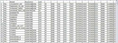
View File all lcd led panel data all lcd led panel data Submitter Vijay Arockia Raj Vijay Submitted 11/28/2017 Category Plasma, LCD, Led and CRT TVs
-
Versão 1.0.0
13 downloads
all lcd led panel data -
https://youtu.be/3E5sO9QjtX0

-
- 1
-
-
dúvida controle sony PS4\JDM030\funciona apenas no PC
Vijay Arockia Raj Vijay respondeu o tópico de m4yur1 em Vídeo Games
reinstall all connectors -
em análise firmware eprom LENOVO - D1960WA
Vijay Arockia Raj Vijay respondeu o tópico de arieluyendyk em Monitores e Projetores
https://eletronicabr.com/files/file/18606-lenovo_d1960wa_10182-eletronicabrcomzip/ -
dúvida preciso regravar bios do EC do notebook
Vijay Arockia Raj Vijay respondeu o tópico de internautacesar em Notebook's
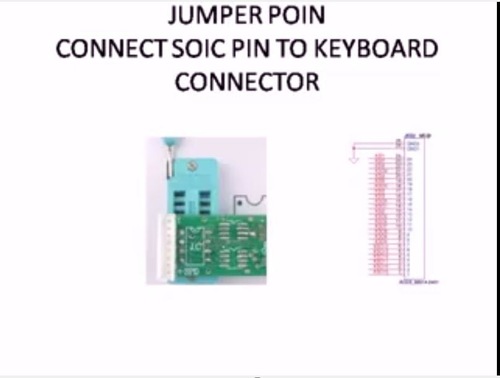
https://eletronicabr.com/files/file/26436-programming-kbxxxxx-with-programmer-rt809f/ -
doc programming kbxxxxx with programmer rt809f
Vijay Arockia Raj Vijay postou um arquivo em Eletrônica
Versão 1.0.0
49 downloads
programming kbxxxxx with programmer rt809f -
doc programming kbxxxxx with programmer rt809f
Vijay Arockia Raj Vijay postou um tópico em Gerenciador de arquivos
View File programming kbxxxxx with programmer rt809f programming kbxxxxx with programmer rt809f Submitter Vijay Arockia Raj Vijay Submitted 11/28/2017 Category Electronics -
Impressora xp214 nao liga
Vijay Arockia Raj Vijay respondeu o tópico de rafaxelias em Casos resolvidos - Impressoras e Copiadoras
check sda scl volt -
lower than 100ohms is short
-
dúvida Monitor LCD AOC tft17w80PSA fonte queimada
Vijay Arockia Raj Vijay respondeu o tópico de adclfernando em Monitores e Projetores
modifi with universal module -
dúvida Fonte assimétrica LW-k305D 30V/5A
Vijay Arockia Raj Vijay respondeu o tópico de jorgedompe em Ferramentas para eletrônica
in my experience -
dica fonte de bancada barata e eficaz
Vijay Arockia Raj Vijay respondeu o tópico de lealtec eletronica em Ferramentas para eletrônica
link???? -
em análise dell inspiron 1526 /48.W001.011
Vijay Arockia Raj Vijay respondeu o tópico de fabricio nunes dos santos em Notebook's
flash firmware -
resolvido Samsung Galaxy Ace4 Neo SM G318ML/DS "não registrado na rede"
Vijay Arockia Raj Vijay respondeu o tópico de Laurysson em Casos Resolvidos - Celulares, Smartfones
check sim connectors- 7 respostas
-
- 1
-

-
- não registrado na rede
- ace4
- (mais 1)
-
resolvido Notebook Itautec w7510 com luz vermelha
Vijay Arockia Raj Vijay respondeu o tópico de Nathã C Souza em Casos resolvidos - Notebooks
check adapter

SOBRE O ELETRÔNICABR
Técnico sem o EletrônicaBR não é um técnico completo! Leia Mais...